Detection Technology
Instruction Manual of Loop Resistance Tester
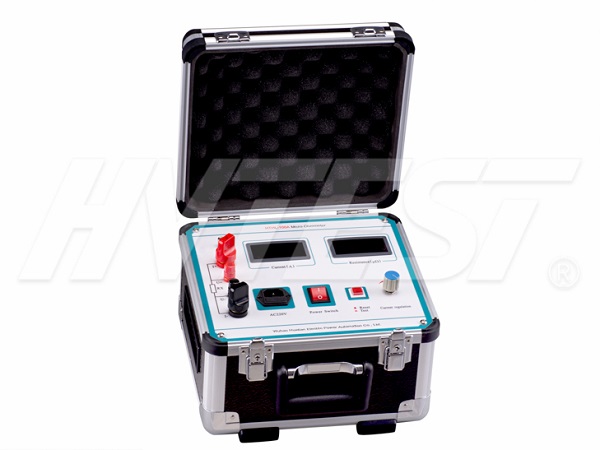
The loop resistance tester is suitable for testing the contact resistance value of the main contact of the high and low voltage switch, and the DC resistance value of the high and low voltage cable circuit. It is refined with advanced high-power switching power supply technology and advanced electronic circuits. It is a special testing instrument for high and low switches, cables, wires and welding seam contact resistance.

1. Connection instructions
There are four on the front panel: a, b, A, and B, a and b are current output wires, connect thick test wires, red and black correspond to colors; A and B are voltage measurement terminals, wiring test wires, red and black correspond to plug colors .
2. Parameter setting
There are three setting parameters: measuring current, alarm resistance, and compensation resistance. The default measurement current is 20A, the alarm resistance is 100mΩ, and the compensation resistance is 0.
When setting parameters, press the setting key in the initial state to enter the measurement current setting state, and adjust the measurement current through the up and down keys; press the setting key again to enter the alarm resistance setting state, and adjust the alarm resistance through the up and down keys; press again Press the setting key to enter the compensation resistance setting state, and adjust the compensation resistance through the up and down keys; press the setting key again to end the setting process and save the modified value.
Customers can set the measuring current and alarm resistance according to their needs during use. When there is a deviation between the measurement result of the instrument and the actual result value, the displayed value can be modified by modifying the compensation value.
3. Measurement
When measuring the grounding resistance of low-voltage equipment, use the matching low-voltage test wire (thin). When measuring the high-voltage loop resistance, use the matching high-voltage test wire (thick). Clamp the test clip on both ends of the conductor to be measured according to the standard requirements. Click Start, the system will automatically adjust the current to the set current value, measure the conductor resistance after stability, and automatically correct the test contact resistance. If the measured resistance value is greater than the set alarm resistance value, the system will prompt unqualified and accompanied by an audible alarm. Press the stop button, the system returns to its original state, and the next operation can be performed.
4. Restore the default parameters
When the instrument causes a program error due to interference or other reasons, when the instrument is turned on, it displays garbled characters or the displayed value is not the set value or other incorrect values. After turning on the instrument, press the "up" and "down" keys at the same time, the system will Restore the default setting value, the default setting measurement current is 20A, the alarm resistance is 100mΩ, and the compensation resistance value is 0.
Loop resistance tester wiring | 2021/12/29 | reading779time Operation precautions for DC resistance tachometer | 2021/12/28 | reading858time return

