Detection Technology
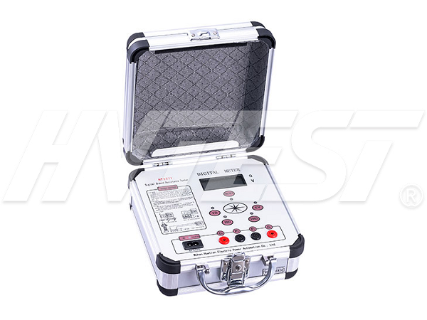
How to use the ground resistance tester
(1) Before the measurement, arrange the ground electrode E' to be measured with the potential probe P' and the current probe C' in a straight line, the distance between them is 20m, and P' is inserted between E' and C', P' and C 'Insert 0.5-0.7m underground, and connect E', P' and C' to the corresponding terminal of the instrument with special wires.
(2) When measuring, put the meter in a horizontal position and check whether the pointer of the galvanometer points to the center line. If it is not pointing on the center line, the pointer of the galvanometer can be adjusted to the center line with the zero adjustment screw.
(3) Set the magnification scale to the maximum multiple, slowly turn the generator crank, and rotate the measuring dial to balance the galvanometer pointer. When the pointer is close to the center line, increase the rotation speed of the generator crank to make the When the rotating speed of the generator crank reaches 120r/min or more, adjust the measuring dial so that the pointer is placed on the center line.
(4) If the reading of the measuring dial is less than 1, the magnification scale should be set to a smaller multiple, and then re-adjust the "measuring dial" to get the correct reading. When the pointer is completely balanced and points to the center line, multiply the reading of the dial by the magnification scale, which is the measured resistance value.

Grounding Resistance Tester Measurement Precautions
(1) During measurement, the grounding device line should be disconnected from the protected equipment to ensure accurate measurement.
(2) If there is a metal pipe or cable connected to the ground electrode under test near the measuring probe, the potential of the entire measuring area will have a certain equalizing effect, which will affect the measuring result. At this time, the distance between the current probe C and the above-mentioned metal pipe or cable should be greater than 100m, and the distance between the potential probe P' and the above-mentioned metal pipe or cable should be greater than 50m. If the metal pipe or cable is not connected to the ground loop, the above distance Can be reduced by 1/2 to 2/3.
(3) When the sensitivity of the galvanometer is too high, the potential probe P' can be inserted into the soil shallower; when the sensitivity of the galvanometer is insufficient, the soil between the potential probe P' and the current probe C' can be injected with water moist.
(4) When the distance between the ground electrode E and the current probe C' is greater than 20m, the position of the potential probe P' can be inserted outside the straight line between E' and C', and the measurement error can be ignored at this time; when When the distance between the ground electrode E' and the current probe C' is less than 20m, the potential probe P' should be inserted between the straight line between E' and C'.
Generation of partial discharges in transformers | 2022/2/3 | reading2418time Technology of Insulation Resistance Tester | 2022/2/2 | reading2522time return

