Detection Technology
Instructions for use of circuit breaker tester
1. Wiring method of circuit breaker tester.
(1) Fracture connection method
Measure the wiring method of vacuum, sulfur hexafluoride, and oil-less three-phase three-break high-voltage circuit breakers.
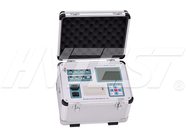
When detecting a three-phase high-voltage circuit breaker with only three fractures, first connect the three-phase fractures of the high-voltage circuit breakers A, B, and C to the red wiring of the instrument A, B, and C (choose the corresponding type of displacement sensor to install). The other one is connected with the corresponding black wiring plug on the corresponding end of the instrument panel.
(2) Wiring method for opening and closing control
During the field test, if the internal power supply of the instrument is used, the closing control line (red), opening control line (green), and common line (black) are connected to the “opening and closing control” port (aviation plug) on the instrument panel. When dividing +, closing +, and negative output, generally must be connected in front of the auxiliary switch contact (which can effectively protect the coil and the instrument). When wiring, pay attention to cut off the operating power of the high-voltage switchgear (disconnect the knife guillotine or unplug the fuse) to avoid conflict between the two power sources and damage the instrument.
(3) External trigger wiring
"Close control line point" and "Open control point" are the normally open contacts of two pairs of relays respectively. When the switch instrument starts measuring, the corresponding relay normally open contacts of "Close control" and "Open control" change In a closed state, the switch under test will act.
Before wiring, users should carefully analyze the wiring according to the wiring diagrams of various high-voltage switch control panels. Be careful to turn off the DC power supply of the instrument when wiring to avoid conflict between the two power sources and damage the instrument.
After all the wiring and parameter settings of the circuit breaker tester are completed, press the close or open button to operate.
Third, if low voltage test or reclosing test operation is required, after entering the special test main menu, select the corresponding submenu and press the confirm key to operate.
Fourth, after the result test is completed, the instrument processes the data and directly displays the test result. Press the confirm key to enter the next page.
Fifth, in the view main menu, there is a submenu of travel time curve or current time curve. Press the enter key to view the travel time curve and current time curve. And can use the axis to analyze the stroke and speed.
Sixth, after the test results are output: move the cursor to print; press the confirm key, the circuit breaker test instrument panel mini-printer prints the currently displayed results, which is convenient for selective output and printing. In the main file menu, select Print All to print all the contents of the current test.
Earth Grid Ground Resistance Tester | 2021/9/25 | reading667time How to use the loop resistance tester | 2021/9/24 | reading632time return


