Detection Technology
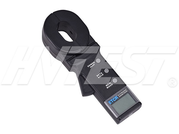
How to use the clamp ground resistance tester
1. Multi-point grounding system
For multi-point grounding systems (such as power transmission system tower grounding, communication cable grounding systems, certain buildings, etc.), they are connected by overhead ground wires (the shielding layer of communication cables) to form a grounding system. See below. When measuring with a clamp meter, its equivalent circuit is as follows:
Among them: R1 is the predicted grounding resistance.
R0 is the equivalent resistance of the grounding resistance of all other towers in parallel.
Although, from the strict grounding theory, due to the existence of the so-called "mutual resistance", R0 is not a parallel value in the usual electrotechnical sense (it will be slightly larger than the parallel value in the electrotechnical sense), but, Since the grounding hemisphere of each tower is much smaller than the distance between the towers, and after all, the number of grounding points is large, R0 is much smaller than R1. Therefore, it is reasonable to assume that R0=0 from an engineering perspective. In this way, the resistance we measured should be R1.
Several comparative experiments with traditional methods under different environments and different occasions have proved that the above hypothesis is completely reasonable.
2. Clamp-on ground resistance tester limited point grounding system
This situation is also more common. For example, some poles and towers are connected to each other by overhead ground wires; for example, the grounding of some buildings is not an independent grounding network, but several grounding bodies are connected to each other through wires.
In this case, if R0 in the above figure is regarded as 0, it will bring a large error to the measurement result.
For the same reason as above, we ignore the influence of mutual resistance, and connect the grounding resistance in parallel to the equivalent
The resistance is calculated according to the calculation method in the usual sense. In this way, for a grounding system with N (N is small, but greater than 2) grounding bodies, N equations can be listed:
Among them: R1, R2,...RN are the grounding resistances of N grounding bodies we require.
R1T, R2T,...RNT are the resistances measured on each grounding branch with a clamp meter.
This is a nonlinear equation system with N unknowns and N equations. It has a definite solution, but it is very difficult to solve it manually, even impossible when N is large.
To this end, please purchase our company's limited point grounding system solution program software, and users can use office computers or laptop computers for machine solution.
In principle, in addition to ignoring the mutual resistance, this method does not have the measurement error caused by ignoring R0.
However, the user needs to pay attention to: In your grounding system, there are several grounding bodies connected to each other, and the same number of test values must be measured for the program to solve, not more or less. The program also outputs the same number of grounding resistance values.
2. Single point grounding system
From the principle of testing, the clamp meter of the clamp-on ground resistance tester can only measure the loop resistance, and cannot measure the single-point grounding. However, users can use a test wire and a grounding electrode near the grounding system to artificially create a loop for testing. The following introduces two methods of measuring single-point grounding with a clamp meter. This method can be applied to occasions where the traditional voltage-current method cannot be tested.
⑴. Two-point method
Find an independent grounding body RB with good grounding near the tested grounding body RA (such as nearby water pipes, buildings, etc.). Connect RA and RB with a test wire.
Because the resistance measured by the clamp meter is the series value of the two grounding resistances and the resistance of the test line.
RT=RA+RB+RL
Among them: RT is the resistance measured by the clamp meter.
RL is the resistance of the test line.
Connect the test line to the end to measure the resistance RL with a clamp meter.
Therefore, if the measured value of the clamp meter is less than the allowable value of grounding resistance, then the grounding resistance of the two grounding bodies is qualified.
⑵. Three-point method
Find two independent grounding bodies RB and RC near the tested grounding body RA.
Step, connect RA and RB with a test line, as shown in the figure below. Use the clamp meter to read data R1.
In the above three steps, the readings measured in each step are the series value of two grounding resistances. In this way, you can easily calculate each ground resistance value:
Because: R1=RA+RB R2=RB+RC R3=RC+RA
So: RA=(R1+R3-R2)÷2
This is the ground resistance value of the grounding body RA. In order to facilitate the memorization of the above formula, the three grounding bodies can be regarded as a triangle, and the measured resistance is equal to the resistance of the adjacent side plus the resistance of the opposite side divided by 2.
The ground resistance values of the other two grounding bodies used as reference objects are:
RB=R1-RA RC=R3-RA
Precautions for partial discharge tester | 2021/9/2 | reading779time Six precautions for DC high voltage generators | 2021/9/1 | reading727time return


