Detection Technology
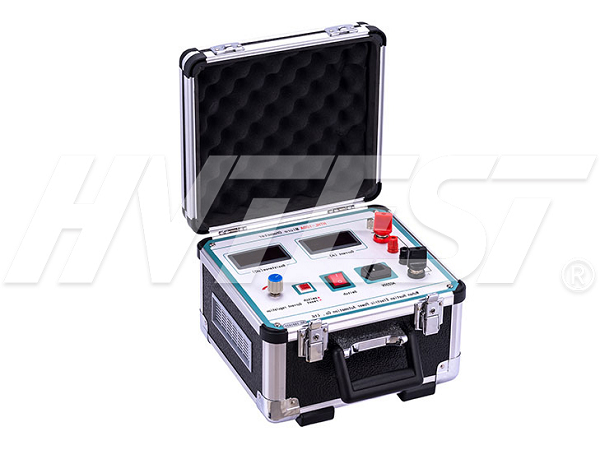
Loop resistance tester testing process
The loop resistance tester is a testing device used to measure the contact resistance and loop resistance of switches, circuit breakers, transformers and other equipment. It adopts a typical four-wire measurement method, by outputting a direct current, applied between the two terminal buttons of the tested body, and measuring the voltage drop generated by the current flowing through the tested body, and then through the voltage and current The ratio gives the DC resistance of the measured body.
1. Connect the test line to the instrument and clamp the tested product.
2. Connect the ground wire (you can also clamp the ground wire clip to the box. The insulation resistance tester is commonly known as a shaker. The megohmmeter is mostly powered by a hand-cranked generator, so it is also called a shaker. Its scale is based on megohms. (MΩ) as a unit. It is a measuring instrument commonly used by electricians. It is mainly used to check the insulation resistance of electrical equipment, household appliances or electrical circuits to the ground and between phases to ensure that these equipment, electrical appliances and circuits are working in normal conditions. Avoid electrical shock, casualties and equipment damage. The metal part of the handle).
3. Plug in the 220v power supply, turn on the power switch, and enter the test duration.
4. Select the test current gear.
5. If the measured current does not reach 100a/20, the high-voltage insulation resistance tester is actually used to measure the insulation resistance of various transformers, motors, cables, switches, electrical equipment and insulating materials. 0a, or zero, you should check whether the connected loop is well connected.
6. If the measurement time is too long and the power supply is overheated, it will carry out active protection. The power supply can be closed for a period of time (approximately 10-20 minutes) to cool the power supply before it can be re-applied.
7. After one measurement, the machine displays the test results, press the print button to print at this time, and press the test button to retest.
8. The test current gear must be selected before starting the test! (models with current selection).
9. The time distance between the two tests is not less than 30 seconds.
10. It is recommended to take the average of three tests (the grounding resistance tester abandons the traditional manual hand-cranked power generation work method, adopts the largest large-scale integrated circuit, and applies the DC/AC conversion technology to measure the three-terminal button and four-terminal button. A new type of digital grounding resistance tester combined into one model. The error of the test value caused by oil stains or poor contact on the outside).
11. If the current line is disconnected during the test, the instrument will automatically identify it and turn off the current output control and prompt ‘please check the line’.
On-site test method of zinc oxide arrester tester | 2021/5/27 | reading733time How is the circuit breaker tester wired? | 2021/5/26 | reading668time return


