Detection Technology
How is the circuit breaker tester wired?
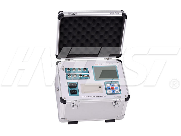
In the power test work, it is often necessary to test the characteristics of high-voltage circuit breakers, and a circuit breaker dynamic characteristic tester is needed. Because of its simple use and powerful functions, this device is welcomed by the majority of power users. When using this equipment, you need to do the wiring work carefully. Today, I will give you a brief introduction to how the circuit breaker dynamic characteristic tester is wired!
After the instrument arrives on site, first connect the protective ground of the instrument to the field ground before starting to learn other wiring and operations; after the test, turn off the power of the instrument and equipment, then disconnect other wires, and then remove the ground wire. When the opening and closing time control power supply is provided by the internal management of the instrument company, the control and power supply in the box can be controlled by disconnecting the tested switch. Usually the temperature control in the control box is used as the fuse connecting the power supply to the control bus, but it cannot be timely Switch off the energy storage power supply of the research institute.
The internal instrument can only provide direct current, "trigger" mode and internal power supply device. If the scene is to swap the switch operating mechanism, use "external" trigger. When used as an external power supply for the field control sub-switch, "power control" is neither wired. Make a single test switch together, "externally trigger" the two wires, and then close the two ends of the coil; make a single test switch point, "externally trigger" the two wire ends, and then open the coil. When the operation uses an external power source, use the "external trigger" mode. Whether the external trigger mode switching mechanism can be AC or DC test. When using an external trigger, there is no sub switch to control the power supply wiring.
Traditional speed sensors usually use sliding wire resistors or photoelectric information sensors (divided into two kinds of grating and photoelectric encoder), these methods are composed of two parts of student movement and static content. When measuring the speed, they can be installed on the moving functional parts (moving contact or lifting rod) and the stationary parts (general cap holder or switch base) of the switch respectively, and we need to cooperate with us. In this way, it is necessary to make a lot of research on different installation engineering brackets for different switches of the enterprise, and it is difficult to install and disassemble on-site construction.
Loop resistance tester testing process | 2021/5/26 | reading709time The safe use of the ratio group tester | 2021/5/25 | reading697time return


