Detection Technology
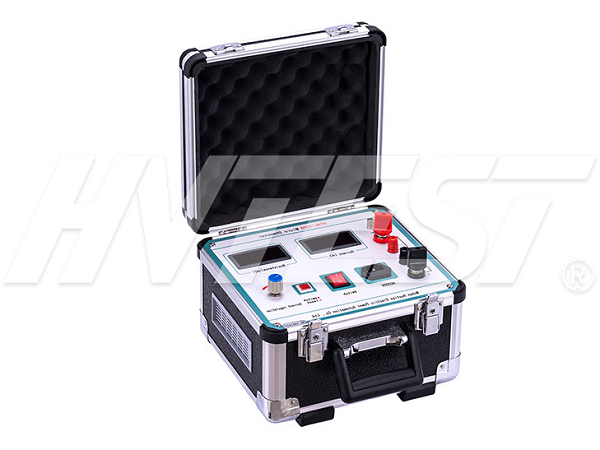
The loop resistance tester encountered a problem
It is inevitable that there will be problems in the long-term use of the loop resistance tester. This does not mean that there is a problem with the quality of the products produced by the manufacturer, because no matter what is used for a long time, there will be some minor problems. Although it will not affect the work for a while, if it is not handled in time, minor faults will occur. It has become a big problem, so it is important to learn some simple repair methods by yourself!
1. Phenomenon: When the fan is connected to 220V AC power supply, the fan is silent, and the "test switch" is pressed once, the ammeter and micro-ohm meter have no display.
Analysis: The 220V AC power supply is unavailable, and the fuse is not installed or fused.
Solution reference: check and eliminate. (100A instrument insurance is not less than 6A, and then contact the factory to solve it. (Never connect to DC or 380V AC power)
2. Phenomenon: Press the "test switch", the ammeter displays no current, and the micro-ohmmeter* displays "1" in the high position.
Analysis: The 100A current loop is not connected properly. The subject switch was not closed.
Solution reference: check the test line, reconnect, and re-clamp. Close the switch.
3. Phenomenon: The test current is normal, and the micro-ohm display is abnormal and does not repeat.
Analysis: The voltage signal circuit is in poor contact, and it is always on and off. The measured resistance itself is not in good contact, and the resistance value changes.
Solution reference: Ensure good and reliable contact. Check and rule out.
4. Phenomenon: The test current is normal, and the micro-ohm meter shows a negative value.
Analysis: The voltage clamp is misplaced, and the positive and negative connections are reversed.
Solution reference: correct, it should be: P1+, P2|.
5. Phenomenon: The output current is dozens of times less than 100A.
Analysis: The power supply voltage is too low, the internal resistance of the power line is large or the contact is poor, and the voltage drop is too large when there is a DC output, and it cannot reach 190V. The terminals C1 and C2 are loose. The circuit under test and the test wire clamp are in poor contact.
Solution reference: Use a qualified power supply, use a power cord that is too long and thin, and deal with the circuit under test to eliminate poor contact. Use proper force when twisting the terminals C1, C2, P1, P2. (The test current is at 30A, the test value is credible)
6. Phenomenon: The test current is normal, and the micro-ohm value* displays "1" in the high position
Analysis: The position of the voltage clamp is wrong. The resistance of the tested circuit exceeds 2000□□. The voltage signal line is broken or not connected.
Solution reference: handle the voltage signal circuit, clamp the voltage clamp correctly. When the range is exceeded: use a multimeter to measure the voltage values of P1 and P2, and the resistance value = voltage value/current value.
7. Phenomenon: During the calibration test, sometimes the displayed value fluctuates greatly.
Analysis: During the verification test, the test wire is in the form of an inductance coil and is not scattered.
Solution reference: Pull the test line apart to reduce its inductance and mutual inductance.
Three-channel DC resistance tester wiring | 2021/6/12 | reading694time Precautions when using partial discharge detector | 2021/6/11 | reading691time return


