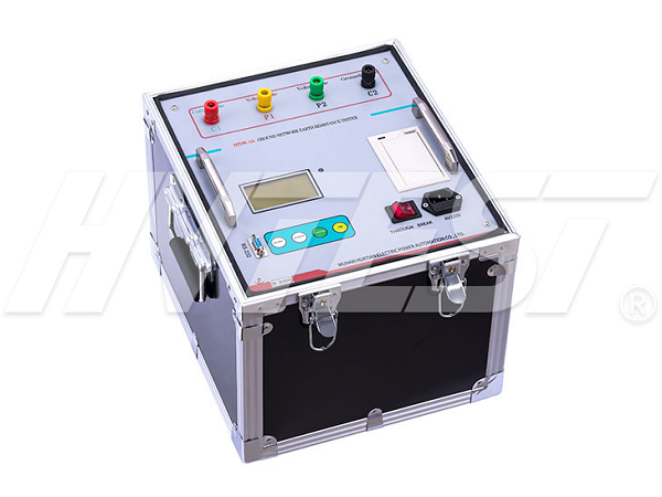
Detection Technology
Large ground measurement analysis
When measuring grounding equipment, the error of the test results is large due to various disturbances, such as unbalanced zero sequence current and rf. The grounding impedance of especially big ground net.through usually is very small (usually less than 0.5 Ω). The relative error caused by interference is large. In order to reduce the impact of field interference, two methods are mainly used, one is to increase the test current, and the other is to use different frequencies. The first is to add tests. The current is used to increase the signal voltage and signal current, thereby increasing the SNR and reducing the measurement error. This method is cumbersome due to the large test current used (DL/t475-2006 is recommended for less than 50A).
This paper introduces a method to measure the grounding resistance of grounding grid. Under the condition of measuring current frequency and system power frequency, the method can obtain stable and reliable measurement results. The source and characteristics of external interference are analyzed, and the simulation test and the field are combined. The influence of the test current frequency and the arrangement of measuring wires on the Z, R and X of the test results was discussed.
The ground resistance of the grounding network is measured by the power frequency current method and the other frequency current method. The former is a traditional method. The power frequency test current, the test power supply capacity, the cross-sectional area of the current line is large and the equipment is heavy. As the test frequency is closer to the power supply frequency, the technical difficulty of the measuring instrument in hardware and software is greater. Therefore, the test frequency of most of the hetero-frequency test instruments is far away from 50Hz, hetero-frequency test results and power frequency test. The equivalence of the results is noteworthy. First, a unique hardware and software anti-interference method was developed.

Operating steps and methods
1. The instrument measures the grounding resistance by measuring the ratio of the rise of the potential of the grounding equipment to the current flowing into the grounding equipment.
2. The variable frequency constant current power supply can output sine wave test current with a frequency of 45Hz or 55Hz. The output frequency is controlled by the microcomputer system, and the output is isolated and output through the E and C terminals on the dashboard. The voltage amplifier is very high. The input impedance amplifier amplifies the voltage at both ends of P1 and P2 and sends it to the filter. The current amplifier amplifies the current signal obtained from the ct and sends it to the filter, which is used to filter out interference signals and only allows 45Hz, while the A/D converter USES 55Hz signals to convert the voltage and current signals into digital signals for analysis by the microcomputer system.
3. After the user begins to measure the grounding impedance, the instrument shall first turn on the heterofrequency power supply to make the output frequency 45Hz. After the current is stabilized, the microcomputer system obtains voltage and current waveform data through A/D converter and performs digital filtering to calculate voltage V45 and current I45 and their phase differences, further calculating impedance Z45, resistance component R45 and reactance component X45. Then, the output frequency of the power supply between switching frequencies is 55Hz. After the same steps, the impedance Z55 and the resistance components can be calculated. R55 and the reactance component X55. The average value of Z45 and Z55 is used as the ground impedance of the power frequency, Z50. Finally, the abnormal frequency power supply is turned off and the measurement results are displayed through the LCD screen. Therefore, when measuring the impedance, the instrument will measure the two voltage input terminals, P1 and P2. The ratio of the voltage of the supply to the output current.
Operation method of large current generator | 2020/5/30 | reading982time Troubleshooting of dc high voltage generator | 2020/5/29 | reading994time return

