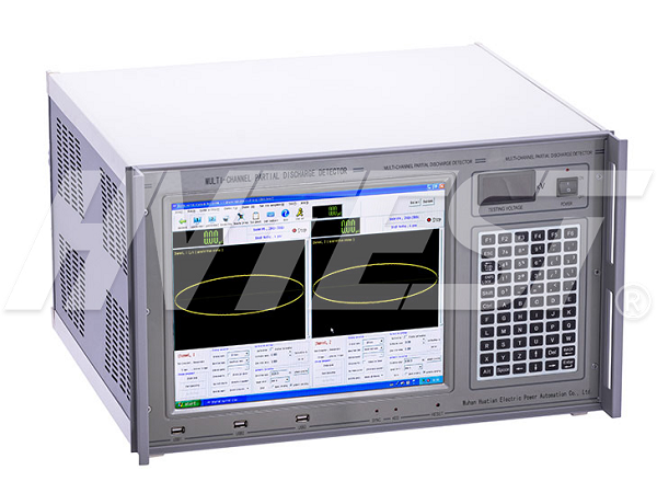
Detection Technology
Partial discharge test operation steps
According to the calculation result of the excitation voltage, the voltage on each side of the tested transformer and the winding voltage of the isolation transformer are measured for the step-up calibration, and the calibration value is recorded.

The test work is carried out in phases, and the test steps for each phase are as follows:
a) Calibrate the discharge volume, record the position of the knobs of the partial discharge instrument, the discharge volume meter readings and background noise.
b) Boost, measure and record according to the requirements of the test pressurization procedure.
c) After the measurement is completed, reduce the voltage, cut off the power, and switch the test wiring.
d) After the three-phase tests are completed, disconnect the test power supply, remove the test wiring, restore the original state of the tested transformer, and end the test.
Experimental preventive and corrective measures
a) If the voltage rises less than U due to the capacity limitation of the test equipment, it can only be raised to U2 for measurement.
b) If the discharge volume exceeds the standard or is unstable during the test, the pressurization time should be appropriately extended for observation, and the initial discharge voltage and extinguishing voltage should be observed for comprehensive judgment.
c) If the discharge volume is small and stable, the pressurization time can be appropriately shortened based on experience.
Matters needing attention in partial discharge test:
Test procedure:
1. Preparation before the test: The surface of the test product should be clean and dry, and its temperature should be consistent with the ambient temperature. The test product should not be subjected to mechanical, thermal and electrical effects before the test.
2. The sensitivity of the verification test circuit should not be less than 50% of the allowable discharge capacity of the test product.
3. The high-voltage lead should be made of a snakeskin tube, and the connection with the test product should be tight, and shielded if necessary.
4. The test product and test equipment should be grounded reliably, preferably at one point, and the grounding wire should be as short as possible.
5. The test circuit should be compact, and the test product should be far away from other objects. Source, identification and suppression of interference:
source:
A. Power interference signal;
B. Interference of the grounding system;
C. Space interference signal;
D. Test the interference signal of the loop itself.
Identify:
A. The test circuit is energized, and the non-boost instrument indication is mainly power interference.
B. Without the test product, the voltage is boosted to the rated value. At this time, the interference mainly comes from the booster and the equipment connected to the high voltage.
C. The test circuit is not energized, and the instrument indication is mainly a space interference signal.
D. Use an oscilloscope to identify other kinds of interference.
inhibition:
A. Analyze the difference from the characteristics of the waveform and read the discharge pulse.
B. Add filters to the power circuit and high-voltage circuit.
C. Select the appropriate frequency band and center frequency for the measuring device.
D. Adopt balance test circuit.
Selection of test transformer | 2021/12/26 | reading805time Dry-type test transformer fault solution | 2021/12/25 | reading841time return

