Detection Technology
Principle of DC resistance tester
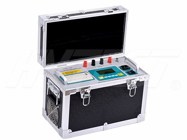
Working principle: There is a constant current source that can generate DC current in the DC resistance tester. When measuring resistance, a constant current is fed into the test object from the I+ and I- terminals, and this current generates a corresponding voltage value on the measured body. This voltage value is taken back to the unit at the V+ and V- terminals. After magnification, the resistance value of the tested product is directly displayed with four and a half LCD numbers.

Precautions
1. When measuring the no-load tap changer transformer, the discharge must be exited before switching the tap changer, and the tap changer can be switched after the discharge instruction is over.
2. It is not allowed to disassemble the wiring during the measurement process.
3. If the charging progress bar and the current display value stagnate for a long time, the measured winding resistance may exceed the current current measurement range, and the current may not reach the preset value. At this time, you can press the "Exit" key to return, reselect the current and try again.
Measuring method of DC resistance tester:
Measuring DC resistance is an important item in the transformer experiment. After measurement, it is possible to check whether the conductive circuit of the equipment has any shortcomings such as poor contact, poor welding, coil faults, and wiring errors. In the actual measurement of medium and small transformers, most of the DC bridge method is used. When the resistance value of the tested coil is more than 1 ohm, a single-arm bridge is generally used for measurement, and the double-arm bridge is used for measurements below 1 ohm. When using the double-arm bridge connection, the potential pile head of the bridge should be close to the resistance to be measured, and the current pile head should be connected to the potential pile head. Before measurement, you should first estimate the resistance value of the coil under test, place the bridge magnification button in the appropriate position, short-circuit the non-test coil and ground it, then turn on the power switch to charge, and press the galvanometer switch after it is fully charged. Quickly adjust the measuring arm, make the galvanometer pointer move to the zero line of the galvanometer scale center, make fine adjustments, and record the resistance value when the pointer stops at the zero position stably. At this time, the measured coil resistance value = multiplying factor ×Measurement arm resistance value. After the measurement is completed, first open the galvanometer button, and then release the power switch.
Test transformer for AC withstand voltage test | 2021/11/23 | reading1018time What are the categories of loop resistance testers | 2021/11/22 | reading723time return

