Detection Technology
DC resistance tester wiring
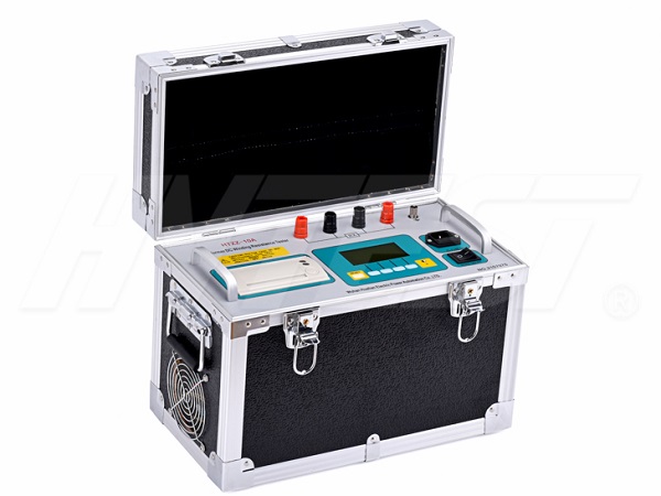
The DC resistance tester is a high-precision, wide-range, high-performance microprocessor-controlled resistance tester, which can test the resistance of 1μΩ~3MΩ and can display 30,000 numbers. The high test speed is 60 times per second, and the test speed is 15 times per second. The accuracy of 0.05% can still be guaranteed, and the reading can be controlled below 3 characters. The standard temperature compensation function can accurately test the resistance of the meter, and the three current modes can meet all kinds of demanding resistance test requirements.

If you want to ensure the use of the DC resistance tester, no link should be ignored, especially the wiring. If there is a problem in this link, the subsequent operations may not be able to proceed normally. You need to pay attention to the following during the wiring process:
1. Connect the instrument to an external AC220 power supply with the power cord, and ground the grounding terminal with the grounding cord.
2. After the three-winding transformer tests the high and low voltage windings, connect the four test clips of the high voltage test line (longer) to the medium voltage side for testing.
3. When testing the two-winding transformer, connect the four test clips (yellow, green, red, black) of the high-voltage test line (longer) to the A, B, C, and O bushings on the transformer. High pressure side. If there are only three bushings A, B, C, the black test clip can be suspended; the other end of the test wire is connected to the terminal of the instrument. Connect the three test clips (yellow, green, red) of the low-voltage test line (shorter) to a, b, c and the bushing on the low-voltage side respectively, and connect the other end of the test line to the instrument on the terminal.
4. For single-phase transformers of DC resistance tester, connect the yellow and green test clips in the high-voltage test line (longer) to the high-voltage side of the single-phase transformer, and connect the green (shorter) test clamps in the yellow and low-voltage test lines to the single-phase transformer. On the low-voltage side of the phase transformer, the other end of the test wire is connected to the terminal of the instrument.
Test process of relay protection tester | 2021/11/10 | reading768time Loop resistance tester to test resistance | 2021/11/9 | reading650time return

