Detection Technology
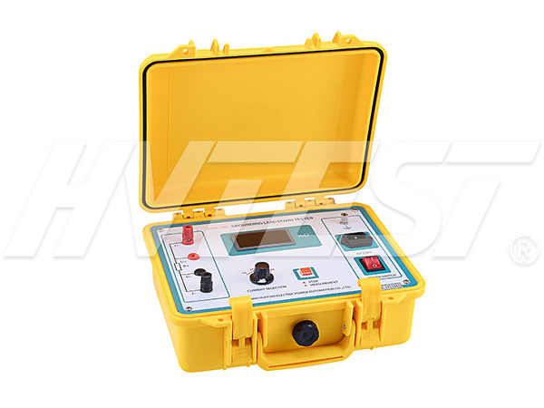
Grounding down conductor continuity tester wiring
In their daily work, power workers often need to use a grounding down-conductor tester to test the electrical integrity of the grounding device. This device has the characteristics of fast boosting, simple and convenient to use, and is very popular among power workers. , Then specifically, how to wire the ground down conductor continuity tester? This article will give you a brief introduction.
Electrical integrity grounding device The grounding device should be the grounding device between various electrical equipment, between the components, and the grounding device of the device, that is, the direct current resistance, also known as the electrical connection of conductivity. Grounding down conductors and grounding electronic equipment are reliable, and efficient connection of network equipment is fundamental to ensure safe operation. The long operation period of the power device of the ground down conductor part of the power device is connected to the network. The connection may be exposed to moisture and other factors. The node may corrode or even break, which leads to the main ground down conductor. It needs a ground network. The grid junction resistance increases, so that the power cannot meet the agreement, so that in the presence of the hidden equipment in operation, the equipment will cause serious operation loss. Part of the ground electrode connected to the ground and the grounding device is corroded or even broken. Therefore, regular electrical ground integrity testing is necessary.
1. Connect as shown in the figure. This instrument has two test wires, a red 50-meter-long wire is placed on the wire reel, a red wire pole has a large fork i +, and a red wire pole. There is a small fork u+, a black 5-meter-long electric pole i- has a big fork on a black electric pole, and the small fork is connected to the black electric pole u-.
2. Determine the down conductor that is eligible to connect to the ground network as a reference point.
3. Use the instrument with two self-measurement wires (50m, 5m) wire holders inserted into the end of the instrument, with end clamps to clamp the test and measurement points to the reference point (refer to which, in the black point test clamp , Each test point in the red test fixture is).
4. In order to make the measurement data correct, please try to clean the contact surface of the measurement point.
5. After the wiring check is confirmed, connect 220v AC, turn off the power switch, and the meter will enter the power-on state. Press the "Measure" button to start the test. The measured resistance value is displayed in the middle of the screen display area as the on-resistance value in m.
6. The "Measure" button pops up, the device test is over, turn off the power, put the test lead into the folder, and put it into the accessory bag.
The ground down conductor continuity tester is a relatively conventional high-voltage power test equipment. In daily work, electric workers need to be proficient in the wiring method of this equipment and get twice the result with half the effort.
Precautions when using the vacuum tester | 2021/9/27 | reading723time How to use zinc oxide arrester tester | 2021/9/26 | reading657time return


