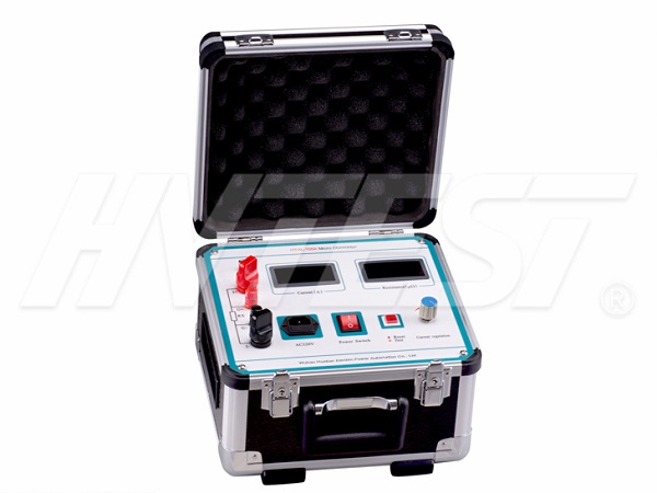
Detection Technology
Principle test of loop resistance tester
Now the loop resistance tester adopts the four-terminal method to test, and the high-frequency switching power supply generates a test current greater than 100A. When the measurement button is pressed, the high-frequency switching power supply outputs a test current greater than 100A, and the sampling circuit starts to input the voltage at the same time. The voltage of the internal current shunt and the internal current shunt are sampled, the obtained signal is amplified by the amplifier, the analog signal is converted into a digital signal by the A/D converter, and then the data is filtered, calculated and processed by the microprocessor, and finally sent to the display for display Get the current and resistance values measured this time.
The above principles work well during normal tests in the laboratory, and when the current test loop is broken or has poor contact, the instrument will determine that the current loop is open according to the voltage on the current shunt. However, when the voltage wiring circuit has poor contact or open circuit, the tester will also display a value. At this time, the following situations will occur:
1) The voltage circuit is open or poorly connected, and there is no strong electric field interference at the test site.
The resistance in the loop of the voltage line of the loop resistance tester. When the voltage line is disconnected, the resistance of R1 is infinite, and sometimes there will be an oxide film or an oil film on the wiring block of the circuit breaker. When the loop resistance voltage test clamp is connected to such a terminal block, poor contact may occur. The tested contact resistance is not infinite, nor is it so small that it can be ignored (for voltage sampling input resistance). In this case, the relationship between the data displayed by the loop resistance tester and the resistance value data of the actual test product is as follows:
Suppose the resistance of the test product is Rx, the input internal resistance of the voltage sampling loop is Ri, and the current sampling is not affected. The value displayed by the instrument = Rx*Ri/(R1+Ri), which is smaller than the actual test resistance. If the resistance value Rx of the test sample has exceeded the safe range at this time, the value displayed by the instrument may be within the qualified range. At this time, it is easy for the test personnel to make a misjudgment and cause a safety hazard.
2) When the voltage circuit is open or has poor contact (the contact resistance R1 is infinite when the circuit is open)
At this time, the charged bus bar interferes with the two voltage test lines through the capacitance with air as the medium. Due to the interference, the differential mode voltage appears at both ends of the voltage acquisition line of the loop tester. If the interference is large, the loop resistance tester will display a comparison test. If the resistance value of the product is much larger, the tester will judge that there is a problem, and after solving it, the correct value will be obtained.
If the intensity of the interference is not great, and the test value of the instrument is just in the qualified resistance range of the circuit breaker, the tester will generally think that the data is correct. At this time, false judgments will occur, false data will appear, and safety hazards will occur.
How to choose a suitable test transformer | 2021/7/30 | reading679time Detection method of loop resistance tester | 2021/7/29 | reading742time return


