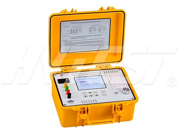
Detection Technology
How to use transformer on-load switch tester
How to use the transformer on-load switch tester:
1. In the actual measurement, the measured waveform is often worse than the theoretical waveform, especially when there is a winding measurement. This is because the oscillation signal caused by the inductance and capacitance parameters of the transformer winding during the measurement, and the mechanical vibration of the tap switch, make the The measured waveform shows some fluctuations, which cannot be avoided in the actual test. Some new switches exhibit insulation under low voltage due to the protective oil film on the switch contact points; as well as switches with longer service life and oxidation of the switch contact points, the waveform may be possible during the test, which is also a normal phenomenon. You can switch several times on this gear to make the oxide layer thinner and increase the contact area, and then use the instrument to test, which may avoid this phenomenon.
2. Another phenomenon is the over-range test. For example, if the transition resistance of the test switch is greater than 9Ω, and the measurement is performed when the range is 9Ω, the result will appear as the waveform shown in Figure 21. At this time, the transition resistance indicated by cursor 1 may be normal, and the transition resistance indicated by cursor 2 is displayed as 50.0Ω. This is due to the over-range. Just change the range to 30Ω and perform the test. It is also possible that in the middle of the transition process, the flat and straight lines are both 50.0Ω, which is also the result of over-range, so you only need to change the range to 30Ω.
3. When measuring without windings, without the influence of the distribution parameters of the transformer windings, the waveform will be closer to the theoretical waveform. When the waveform curve measured by the user is not straight, it is mostly due to mechanical transmission, not a problem with the switch or instrument test. If a breakpoint occurs, and the waveform at the breakpoint returns to the bottom, be cautious.
4. Sometimes there is an instantaneous break point when the switch is switched, and the waveform is pressed into an approximately straight line at this time. This situation is caused by the processing of this instrument. When you move cursor 2 to read each point of the three-phase waveform curve, you can also see the change of resistance at each period of switching, but in this case, re-test. When the waveform has an abnormal drop point and the duration is more than 2ms, the resistance value should be checked. If the resistance value exceeds 50Ω, there may be poor contact or looseness. At this time, the test should be repeated many times. In order to judge.
How to wire the volt-ampere characteristic tester? | 2021/7/13 | reading736time The DC resistance tester makes a noise | 2021/7/12 | reading686time return


