Detection Technology
Principle of Insulation Resistance Tester
principle
Principle of Insulation Resistance Measurement Realized by Insulation Resistance Tester
The insulation resistance Rx of the measurement target is calculated by measuring the current I flowing to the target when the voltage V is applied, and then dividing the applied voltage V by the resulting current I.
Low insulation resistance measurement principle realized by insulation resistance tester
The insulation resistance Rx of the measurement target is calculated by measuring the voltage V that occurs at the measurement terminal when the current I is applied to the target, and then dividing the terminal voltage V by the applied current I.
Photovoltaic resistance measurement principle realized by insulation resistance tester
The resistance Rx of the measurement target is calculated by measuring the current I flowing to the target when the voltage V is applied and then dividing the applied voltage V by the resulting current I. (The value of the voltage and current generated by the measurement target will be subtracted from the power generation.)
2. How to use the insulation resistance tester
Insulation resistance resistance measurement
Warning: Do not attempt to measure the insulation resistance on live conductors.
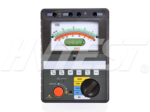
• Make sure that the measurement key is not in the raised position.
• Refer to the table and determine the measurement voltage rotary switch to be set.
• Connect the black test lead to the ground side of the object under test.
• Connect the red test lead to the line to be tested.
• Press the measurement key.
• Read the value after the inductance stabilizes.
*This list outlines how to use the insulation tester. Please refer to the user manual of the product to ensure safe and correct use.
Discharge function
In order to discharge correctly, be sure to perform operations as shown below after measurement.
• If you have not removed the test lead from the object under test, release the measurement key.
• The built-in discharge circuit automatically discharges.
• When the discharge ends, the "discharge mark" on the right side of the display disappears.
*This list outlines how to use the insulation tester. Please refer to the user manual of the product to ensure safe and correct use.
*Please note that the values in the table apply to tests in Japan.
Voltage measurement
Note: The test leads should only be connected to the secondary side of the circuit breaker.
Do not press the measurement key when measuring voltage.
• Use the rotary selector to select the V function.
• Connect the black test lead to the ground side of the object under test.
• Connect the red test lead to the line side of the circuit breaker.
• Read the value after the indicator light stabilizes.
Resistance measurement
Before the measurement, perform zero point adjustment to eliminate the wiring resistance of the test leads and other potentially problematic quantities.
• Set the rotary selector to the Ω function.
• Short-circuit the test leads.
•Pull up the measurement key.
• Turn off the measurement key used to hold the measured value.
•Press the zero adjustment knob key.
• Connect the test lead to the ground side of the object under test
•Press the measurement key to read the displayed value.
• Turn off the measurement key after use.
Solution to failure of loop resistance tester | 2021/6/23 | reading770time Dry-type transformer protection measures | 2021/6/22 | reading693time return


