Detection Technology
Operation steps of zinc oxide arrester tester
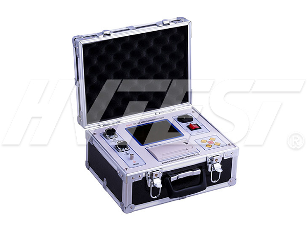
The zinc oxide arrester tester makes the instrument can be used for on-site online monitoring (live test) and laboratory (power outage maintenance) testing of zinc oxide arresters. It can measure the full current and resistive current of the zinc oxide arrester under the power frequency voltage to judge the moisture of the MOA insulation and the aging degree of the valve plate. It also has the functions of electrical parameter testing, vector analysis, and harmonic testing.
Steps:
The current measurement of the instrument adopts a direct wiring method to ensure the accuracy of the test data. The voltage measurement adopts three measurement methods: wired, wireless, and no PT. The wireless transmission method completely avoids the need for long laying due to the long distance between the arrester and the PT. Trouble with the distance to the voltage measurement line.
The whole set of instrument is mainly composed of a host, a voltage wireless transmission extension, a four-core voltage test line, a set of current lines, test clips, etc. The following is a laboratory (power outage overhaul) method to explain the actual operation. The first is to test the wiring, the first step is to ground the tester well, and the second step is to connect the voltage signal. At this time, note that the voltage signal test line must be plugged in first. Go to the voltage test hole of the instrument, and then connect the PT secondary side terminal. If you use a wireless transmission extension, you must first connect it to the wireless extension jack. The black clip is connected to the neutral point, and the yellow, green and red clips are respectively connected to the phase voltage (a/b/c). The single-phase high voltage generator we use on site. The third step is to connect the current signal. Same as before, the current must be tested first. Connect the wire to the IA IB IC test terminal of the instrument, and then connect the two ends of the discharge counter. Pay more attention to connecting the lower end of the discharge counter first, and then the upper end of the discharge counter. So far, all the wiring of the test has been completed.
Next, enter the parameter setting module, voltage level, input the voltage level value of the tested product, current input, and select our corresponding current measurement method. The compensation angle is input in the measurement mode without PT. After the setting is completed, we directly enter the wireless test module. This screen displays the actual measured three-phase secondary voltage amplitude, the converted three-phase primary voltage amplitude, the three-phase full current amplitude, and the three-phase resistive current. The peak value, capacitive current peak value, and three-phase fundamental wave, 3, 5, 7, sub-harmonic resistive current peak value and other data can be used to determine whether the test product is qualified. In this interface, press F1 to When the screen is locked, F2 continues to refresh the data, F4 can print the data, or press the store key to save the test results.
We have finished talking about the operation process of the zinc oxide arrester tester using the wireless test function. There is also a PT test. The non-PT test is the same. We will not introduce them in detail. Let’s take a look at the electrical test and vector analysis modules of the instrument. The electrical test module can display the voltage and current amplitude and phase angle, power value and total power factor in real time. The vector analysis module can display the three-phase voltage and current hexagonal vector diagram in real time. It is very convenient for us to analyze the wiring on site.
When using this instrument for testing, it is strictly forbidden to work when the voltage and current exceed the range.
Troubleshooting of On-load Switch Tester | 2021/5/15 | reading680time Capacitance and inductance tester usage details | 2021/5/14 | reading682time return


