Detection Technology
Principle and method of grounding resistance test
Principle and method of grounding resistance test:
When testing the grounding impedance of the grounding device, the current pole should be arranged as far as possible. Generally, the distance between the current pole and the tested grounding device, dcG, should be 4 to 5 times the length D of the tested grounding device (parallel wiring method). In areas with well-proportioned soil resistivity, it can be 2 times or more (triangular wiring method), and the voltage lead length is 0.618 times the current lead length (flat wire wiring method) or current wire (triangular wiring method).
1. Flood level drop method
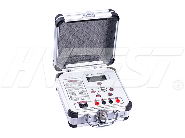
To test the grounding impedance of the grounding device by the electric intelligent loop resistance measuring instrument, the grounding impedance is to be arranged according to Figure 1, and meets the requirements of the arrangement of the test loop.
The current I flowing through the tested grounding device G and the current pole C causes the sky flood level to change. The flood level pole P moves from the side of G to a position 30°~45° with the current loop, every distance d (50m Or 100m or 200m) Test the flood level difference U between P and G once, and draw the straight line of change between U and x. The straight line level is the two flood level points, and the flood level between the line point and the line point is the flood level reduction U of the tested grounding device under the test current. The grounding impedance of the grounding device is:
Z=Um/I If it is really difficult to set the flood level test line and the current line in a position, it can be set in the same way as it, but keep the distance as far as possible.
If it is difficult to determine the flat point of the straight line at the flood level, it may be affected by the tested grounding device or the current electrode C, thinking about extending the current loop; or maybe the underground condition is simple, thinking about other methods for testing and verification.
2. Three-pole method of current-voltmeter
a) Curve method
The prevention of the current line and the flood level line at the same position (same gate) is called the curve method in the three-pole method, as shown in Figure 2; dcG meets the requirements of the test circuit arrangement, dPG is generally (0.5~0.6) dcG. Flood level pole P should be moved three times at the connection position between the tested grounding device G and the current electrode C, and the interval of each movement is within 5% of dcG. When the resultant error of the three tests is within 5%.
The curve method is not suitable for heavy grounding devices. If the environment is limited and must be adopted, care should be taken to keep the current line and the flood level line as far apart as possible to reduce the impact of mutual inductance meshing on the test results.
b) Angle method
As long as the environment permits, the ground impedance test of heavy grounding devices adopts the form of current-flood level line angle arrangement. The dcG meets the requirements of the test circuit arrangement, which is normally 4D~5D, and as far as possible for the hybrid grounding device; the length of dPG is similar to dcG. The ground impedance can be corrected by formula (2).
How to connect DC high voltage generator | 2020/10/26 | reading713time How to use relay protection tester for AC test | 2020/10/25 | reading717time return


