Detection Technology
Grounding resistance method of potential drop
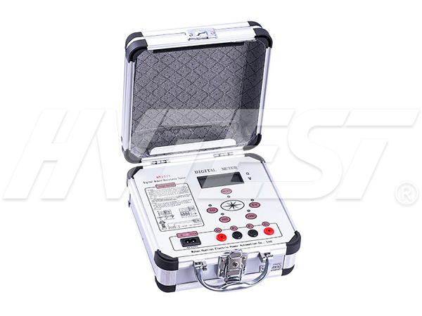
Ground resistance measuring instrument (also called ground resistance test equipment) measurement method:
In order to measure resistance, we need to use a ground resistance meter to apply a voltage between its terminals so that the current circulates through the terminals. One of the terminals is the contact E accessible by the earth system. By definition, the second terminal is actually any other point on the earth that is far away from the first. To perform the measurement, we should hammer the auxiliary electrode H at this time. The second electrode will inevitably have its own ground resistance and resistance area.
1. Measure the ground resistance of electrode E. If the conventional resistance measurement between point E and point H is performed by measuring voltage and circulating current, the sum of the ground resistance of the two electrodes will be obtained instead of the ground resistance of electrode E. This is very important because the H size is very small compared to E due to the conditions of the auxiliary electrode itself, so its contribution to the total resistance may be very important, thus introducing a considerable error.
2. It can be considered that the auxiliary electrode H is far enough away from the grounding system, which is measuring resistance when its corresponding resistance areas do not overlap. In this case, all the volumes outside the resistance area are very approximately at the same potential, which makes it possible to develop the following measurement methods.
Grounding resistance measuring instrument's position drop method:
In order to avoid errors introduced by the ground resistance of the electrode H, a third electrode S is used. Hammer the S rod anywhere outside the E and H zones of influence, and the result is a geometric shape.
This arrangement is called the Fall-of-Potential method, and is the most common method for measuring ground resistance in small and medium-sized systems. In this method, the spacing of the resistance areas is obtained by keeping a reasonable distance between the electrodes. The current circulates in the grounding system E and the auxiliary electrode H, and the voltage between E and the third electrode S is measured. This voltage is the potential drop generated by the test current in the resistance Rx of the grounding system. Can be measured without being affected by the ground resistance of the H rod.
How to use relay protection tester for AC test | 2020/10/25 | reading717time Three types of insulation resistance test | 2020/10/24 | reading688time return


