Detection Technology
Top 5 questions about ground testing
1. What does the word "ground" mean?
The exact definition can be obtained from the National Electrical Code. It is important to remember that the term is often specific to a particular user. In other words, it "implies" the speaker's intention. When conducting a conversation, make sure that the participants are referring to the same thing.
Ultimately, "ground" is an intentional electrical connection to the ground by an electrode that calls the electrical system connected to the ground (i.e., zero) potential. However, the term is also used to refer to the electrodes themselves and the conductors that extend throughout the system to ground the equipment. By extension, "ground" can be simply understood as the third wire in a typical "thermal neutral" power cord. It can also be used to mean unintentional grounding, which is a condition in which the device fails and is "short-circuited." So before you have a meaningful conversation, be sure to use "ground".

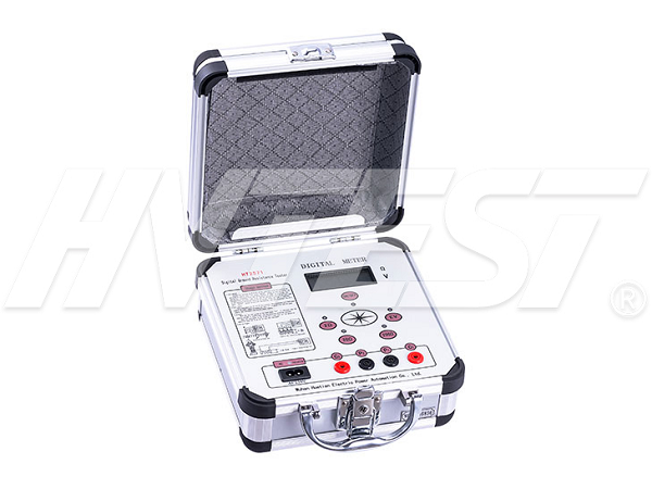
2. How does the ground resistance tester perform the test?
The dedicated ground resistance tester is uniquely designed to handle the function of distinguishing ground tests from the more common measurement types. Unlike familiar test items (motors, transformers, wires and cables), grounding is clearly not a designed circuit, does not limit current to a specific path, and there is no "start" or "end" phenomenon. In addition, a ground resistance test is a volume measurement that must be able to measure the resistance of the soil volume around the earth electrode in a full circle, rather than along a straight path as in a familiar circuit.
Therefore, the grounding resistance tester has a current circuit and a potential circuit. A test current was established between the ground electrode and the current probe by inserting a metal probe into the soil. Similarly, the voltage probe contacts the soil at a distance equal to the resistance of the measured volume and measures the associated voltage drop. Using both voltage and current parameters, the instrument can calculate and display the resistance of the soil to the current from the grounding electrode using Ohm's law. For visualization purposes, the "project under test" can be thought of not only as electrodes, but as "spheres" or "chunks" of soil around them, because the earth's vastness makes it beyond the rest of the earth,
3. Can I use the insulation resistance tester for the same test?
No. This is a common mistake. The insulation resistance tester is designed to measure resistance on the opposite end of the ground resistance tester. No one wants "ground" measured in megabytes! For this reason, insulation resistance tester adopts high test voltage in kV range. Ground resistance testers are limited to low voltages for operator safety. Insulation resistance testers do usually have low voltage, low resistance continuity and are often mistakenly used for "awkward" grounding tests. However, the continuity test can only make arbitrary measurements between the installed electrode and the reference ground, assuming that the reference ground is low (i.e., negligible). Apart from luck, this does not reliably measure the resistance of the earth's fault current to the ground. Moreover, even such arbitrary measurements can be unreliable, as DC continuity tests may be subject to soil transients, common ground currents attempting to return transformers, and electrical "noise" from other sources.
4. The required measurement is resistance. Why can't you use a multimeter?
For the same reason, insulation resistance tester should not be used for continuity range. Use of dc multimeter to measure electrical "noise" in the soil and distortion, multimeter can't provide any methods to verify whether shows resistance represents two convenient point between any of the measured values, that is, using a multimeter to measure grounding electrode and a reference point (such as water pipe system) between soil resistance, but the fault current may have a higher resistance. A true ground tester should follow standard procedures developed in the field with built-in cross-checking that can expose insufficient test conditions and reference ground, assuming that the resistance of the reference ground is low (i.e., negligible).
5. What's the difference between "2", "3" and "4" tests?
Literally, the number of points in contact with the soil. More specifically, these are commonly used terms corresponding to so-called "ground", "potential drop" and "Wenner method" tests, respectively; In the grounding method, contact is made only at two points: the measured ground electrode and a convenient reference ground, such as a water pipe system or a metal fence; In the "potential drop" method, a real ground tester makes contact with a test electrode and a current and potential probe. Using the Wenner method, no grounding electrodes are involved, but the independent electrical properties of the soil itself can be measured using a four-probe setup and accepted standard procedures.
High voltage generator test operation method | 2020/6/20 | reading974time How does the insulation resistance tester work? | 2020/6/19 | reading994time return

