Detection Technology
How does the insulation resistance tester work?
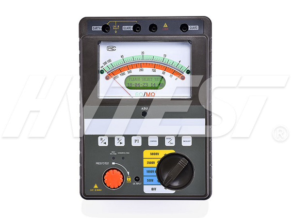
Insulation resistance tester tests system for capacitor and current leakage in cables, generators and motors, high voltage equipment and switch cabinets. Insulation resistance is measured in megohm. Installation, routine maintenance and real-time surge (drop/return) can be checked to prevent potential problems.
The type of device under test and the reason for the test determine which test method you use. Low capacitance test, time and equipment used to determine leakage/absorption of cables and switchgear. Large capacity (long time) equipment and tests are used to determine leaks in large motors, transformers, generators and long cables. Separately test the insulation and the phase and/or winding of each motor, generator or transformer.

What types of tests are available?
Click read/short test - similar to a proof (pass/fail) test to quickly test insulation after installation. The point read/short test is a low capacitance test that applies a test voltage of approximately 60 seconds.
Time resistance/time ratio tests and leakage tests are low capacitance tests that use polarization index (PI) and dielectric absorption factor (DAR) to determine the integrity of cables, transformers, motors, and electrical installations. Absorption current and capacitor leaks were detected almost immediately. These tests provide good short resistance point readings.
Step voltage and dielectric absorption test A high capacitance test that takes several hours to perform due to short meter readings that are inconsistent. These tests collect relative readings and measure the same readings.
Test purposes
Testing is a preventative program that catches insulation problems before they cause overall equipment performance failures. Insulation resistance tests are performed at the time of installation and should be consistent throughout the life of the equipment. Verification tests ensure proper conductor installation and integrity. They quickly test insulation through insulation resistance testers after installation and detect cable system maintenance errors.
Measuring polarization current
The DC voltage insulation resistance/polarization index (IR/PI) test is used to assess quality and determine wear and thermal degradation in insulation, e.g. windings due to coil vibration. PI measurements are not recommended for oil-immersed equipment such as transformers.
The current pulsates at time = 0 and decreases to the insulation conductivity value during the polarization time (Tc). Take two readings (at 1 minute and 10 minutes, respectively). PI = 10 minutes. Insulation resistance reading divided by 1 minute. Insulation resistance reading.
The polarization/depolarization current (PDC) test measures the discharge current flowing through the earthed dielectric material for several minutes. For the first few seconds, the absorption current is set to "high," and for low-capacitance devices, the absorption current gradually decreases to zero. For high capacitance equipment or wet/contaminated insulation, the absorption current should be set and maintained for a long time (without decreasing).
Measuring leakage current
The constant current flowing through the insulation is the conduction current or leakage current. Increase indicates insulation deterioration. To measure high DC voltage, press the test button. Microampere current flows through conductors and insulators. Current is the applied voltage, system capacitance, and total resistance. The reading represents the internal resistance of the conductor plus the insulation resistance.
Measure the leakage current to the ground when the load device is turned on. Single - phase circuit is tested by clamping phase line and zero line. Test the three-phase circuit by clamping all conductors and zero wires (if any). The measured value is any current flowing into the ground surface.
Ground conductor leakage is measured by clamping the ground conductor.
By clamping phase lines, neutral lines, and ground wires together, the earth leakage/imbalance current through the unintentional path can be determined. Leakage of switchboards, bonding connections, or sockets is detected by their unintentional path to the ground (i.e., concrete base, pipe grounding, etc.).
Top 5 questions about ground testing | 2020/6/19 | reading993time Type of insulation resistance tester | 2020/6/18 | reading988time return

