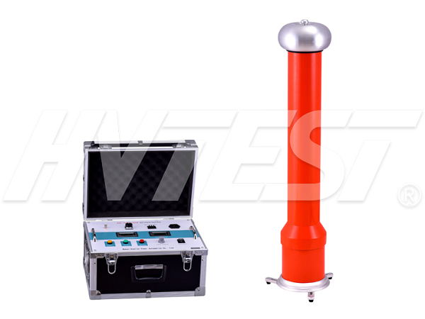
Detection Technology
Principle of dc high voltage generator
The input terminal of the high-frequency transformer receives the mid-to-high-frequency voltage signal and reaches the output of DC high voltage through the voltage doubler rectifier circuit (rectifier silicon stack D and capacitor C). In the figure, R1 is the current measurement sampling resistance, and the current flowing through R1 is the current The current of the overload RL, R2 and R3, are high-voltage measuring resistors, which together form a voltage divider circuit (R3 is the high-voltage arm, R2 is the low-voltage arm), and the DC high-voltage generator assembly structure is: R1, R2 is placed in the DC high-voltage generation The control box of the converter, R3 and the high-frequency transformer, voltage doubler rectifier circuit, etc. are placed in the voltage doubler. The medium-high frequency voltage signal output from the control box is connected to the voltage doubler through a special cable.
The power equipment insulation preventive test includes AC withstand voltage test and DC withstand voltage test. Because the voltage distribution on the equipment insulation is different under the action of DC voltage and AC voltage, the DC withstand voltage test is difficult to achieve in some AC voltages. Insulation strength test plays an important role and becomes an effective supplement to the AC withstand voltage. The DC high-voltage generator is the main equipment for the DC withstand voltage test. To ensure the accuracy and reliability of the DC withstand voltage test, the DC high-voltage generator needs to be periodically calibrated. Based on the basic principle of DC high-voltage generator, this article discusses a number of problems found in the measurement and calibration of this type of equipment in the laboratory, so as to ensure the accuracy and reliability of the value transfer.

DC high voltage generator withstand voltage test procedure
⑴ Before doing the load test, install the high-voltage shielded micro-ampere meter to the high-voltage output on the voltage doubler. And connect the supporting special high-voltage line to the micro-amp meter and the tested product respectively.
⑵ Check whether the instrument, discharge rod, voltage doubler, test sample connection wire and grounding wire are correct. Whether the ground wire connection is reliable. Check whether the high-pressure safety distance meets the requirements. Only then can the high-pressure test of the test product begin.
(3) After checking the DC high voltage generator to confirm that there is no abnormality in the instrument, etc. Turn on the single-phase AC 220V power switch. At this time, the green light is on, indicating that the power is on, and the DC leakage and DC withstand voltage test of the sample can be started.
⑷ Press the red button, the red light is on. . Indicates that the high voltage is connected and the pressure is to be increased.
⑸ Gently adjust the voltage regulator in the clockwise direction, the output terminal will start to increase from zero, and the increase rate is preferably 3-5kV per second to increase the test voltage. For the large capacitance test sample, it needs to be slowly boosted, otherwise it may cause voltage overshoot. It is also necessary to monitor that the charging current of the ammeter does not exceed the charging current of the DC generator, and when it reaches the required voltage or current, record the readings of the ammeter and the voltmeter according to the specified time.
⑹ After the test, reduce the voltage and return the voltage regulator to zero. Then press the green button to cut off the high voltage and turn off the power switch.
⑺ After the test is completed, use the discharge rod to discharge the sample multiple times. After the discharge, you can work close to the sample and disconnect the wire.
Slowly adjust the booster of the small-capacitance sample such as zinc oxide arrester, magnetic blowing arrester, etc. To the desired voltage (current) value, then read the voltage (current) value from the digital display. If you need to measure 75% VDC-1mA on the zinc oxide arrester, the voltage value should be stopped when the current reaches 1000uA (the voltage and current value can be recorded at this time), and then press the yellow button, the voltage will drop to the original 75%, and keep this state. At this time, you can read the value and voltage value of the microampere meter. After the measurement is completed, the potentiometer returns to zero counterclockwise, press the green button, press the red button when you need to boost again Yes; for large capacitance test samples, the boost should be slower, and the charging current of the ammeter needs to be monitored not to exceed the maximum charging current of the generator. The boost speed must be slowed to avoid excessive charging current. After the test, return the voltage adjustment potentiometer counterclockwise to the zero position. Then press the green button to cut off the high voltage. At this time, do not turn off the power supply. The voltmeter shows that there is still a voltage value. This is the stored voltage. Wait for the voltage to drop to about 2000V before the discharge rod can be used for multiple discharges to ensure safety.
How to read a megohm meter | 2020/5/5 | reading1093time Fault of dc resistance tester | 2020/5/4 | reading1139time return

